0
Cart
Order List
Total Price
$0.00
Direct Purchase Available
Measure Sound Better

NEW
Products
Featured Products
Product Lines
Deliver reliable products for acoustic measurement and testing
Sensors
Provides measurement microphones, mouth simulators, ear simulators, and more for accurate acoustic measurements.
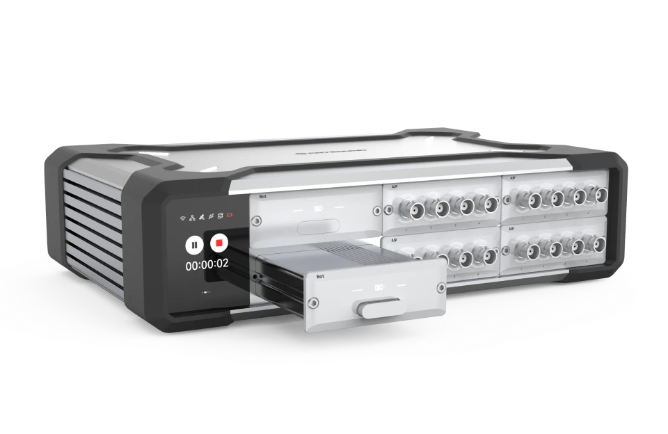
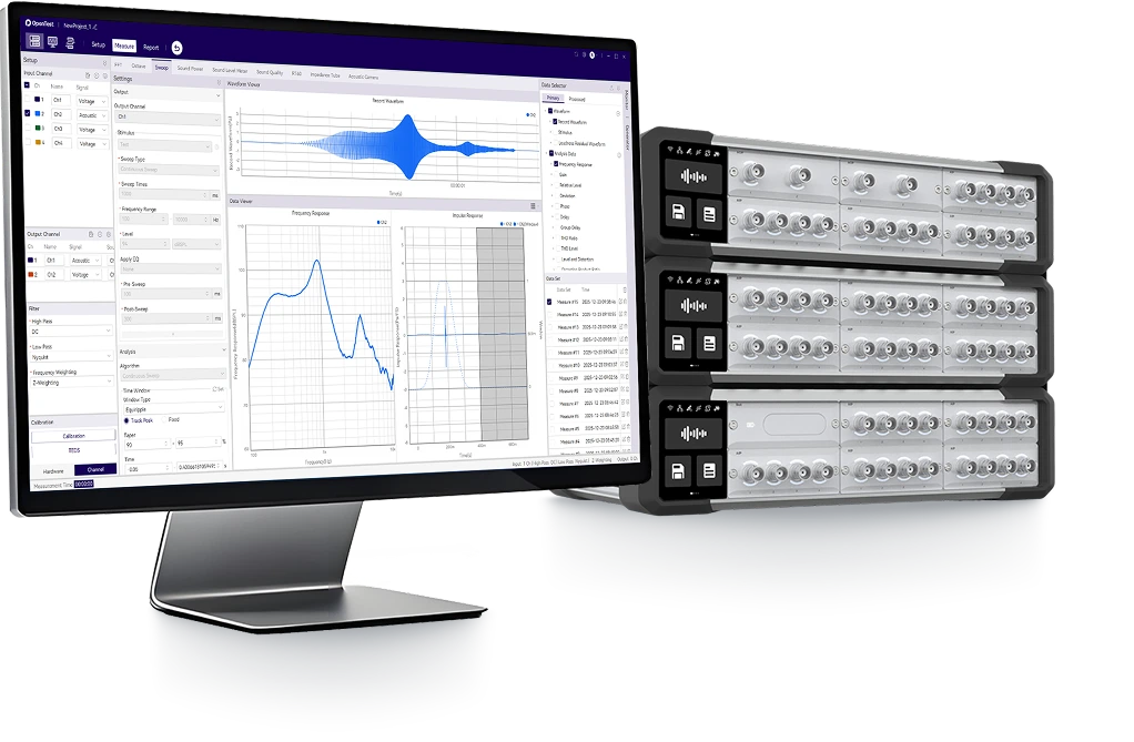
Data Acquisition
Combines hardware and software for high-speed, high-precision signal acquisition, ideal for various acoustic applications.
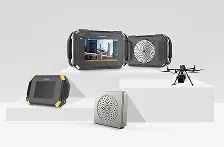
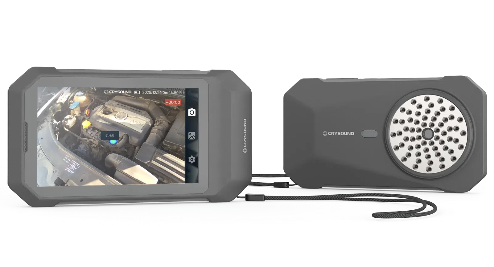
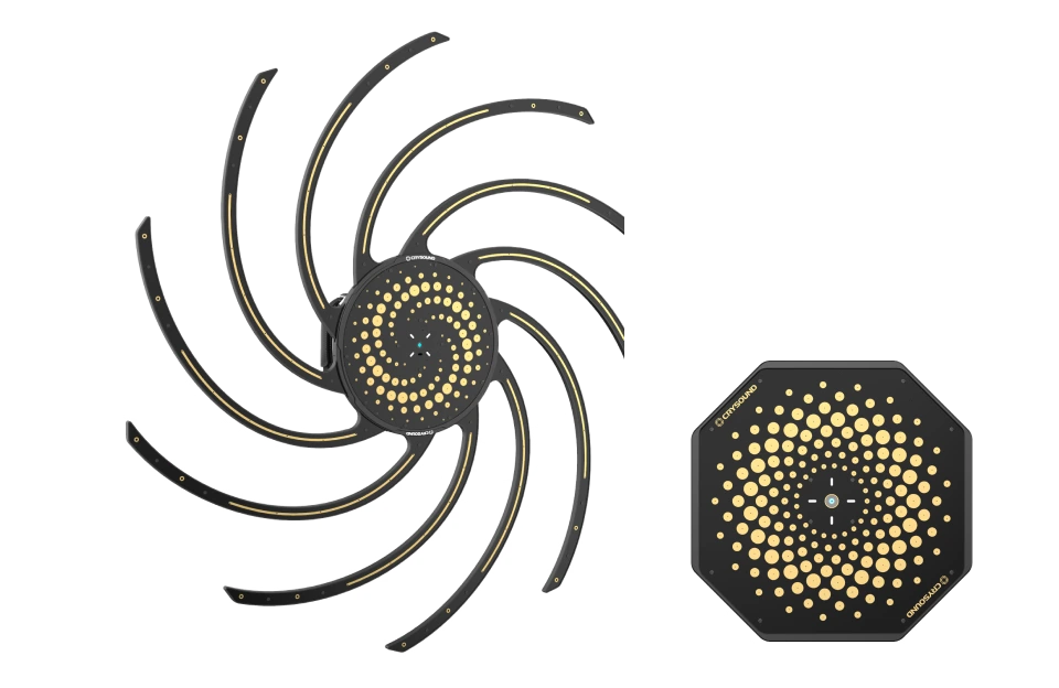
Acoustic Imaging
Offers acoustic cameras for gas leak detection, partial discharge, and fault diagnostics across handheld, fixed, and UAV platforms.
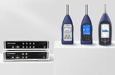
Noise Measurement
Includes sound level meters, noise sensors, and monitoring systems for effective noise measurement and analysis.
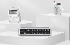
Electroacoustic Test
Delivers complete electroacoustic testing solutions, including analyzers, testing software, and acoustic test boxes.
Solutions
Provide high-quality solutions for the acoustic field
Blogs
Share insights, cases and trends in acoustic testing
Sound Quality
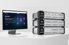
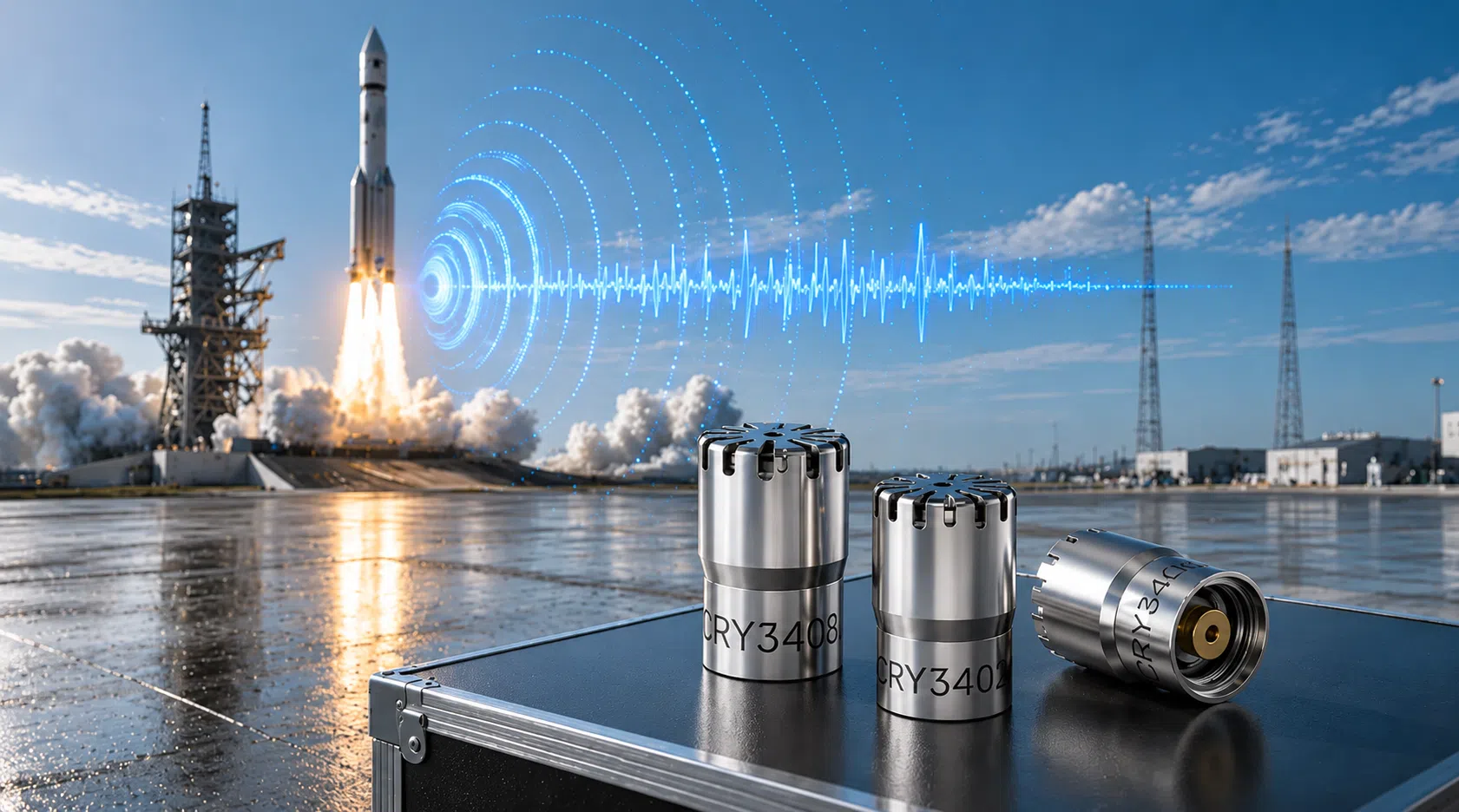
When engineers verify microphones, sound level meters, or high-intensity noise sources above 160 dB SPL, the key question is no longer only "can the sensor survive?" but "can the working standard microphone still measure accurately without adding its own distortion?" High sound pressure level measurements above 160 dB present unique challenges for acoustic testing systems. In this range, microphone distortion can significantly affect measurement accuracy. This article explains how distortion occurs in working standard microphones, how to build a reliable high-SPL test environment, and how to select microphones suitable for 160 - 170 dB measurements. How Does Distortion Occur When SPL Exceeds 160 dB? In high SPL acoustic testing, distortion refers to additional spectral components introduced into the output signal of a working standard microphone due to nonlinear response. These components generally appear as harmonic distortion and noise components. When the sound pressure level exceeds 160 dB SPL, the microphone diaphragm may experience two major effects: Excessive diaphragm vibration amplitude - The diaphragm displacement becomes large enough that it can no longer follow the acoustic waveform with perfect linearity. Generation of additional signal components - Frequency components not present in the original sound field may appear in the microphone output signal. These additional components are defined as Total Harmonic Distortion (THD). Under 160-170 dB high SPL measurement conditions, these nonlinear effects become increasingly significant. As a result, measurement data may appear stable while actually deviating from the real acoustic field. Therefore, in high sound pressure level measurements, distortion control is a critical factor in determining whether the measurement results remain accurate and reliable. What Is a Working Standard Microphone for High SPL Testing? A Working Standard Microphone is positioned between laboratory reference microphones and general measurement microphones. Its performance is defined by international electroacoustic standards such as IEC 61094, ensuring reliable accuracy and stability for industrial high SPL acoustic testing. For 160-170 dB high SPL measurements, the key performance requirement is: Total Harmonic Distortion (THD) ≤ 3% within the specified frequency range at sound pressure levels between 160-170 dB SPL THD represents the ratio of distortion components introduced by nonlinear system behavior in the microphone and measurement chain. For example, if THD = 3%, this means that up to 3% of the measured signal energy may originate from distortion generated by the measurement system rather than the actual acoustic signal. In international electroacoustic standards, THD ≤ 3% is generally considered the acceptable distortion limit for high SPL measurements. Why Use Distortion Curves as a Reference? What Does THD Above 3% Mean? A distortion curve illustrates how the distortion level of a working standard microphone changes as the sound pressure level increases. In high sound pressure level testing, the distortion curve provides one of the most important indicators for evaluating microphone performance. Under 160-170 dB SPL conditions: The diaphragm material may enter a nonlinear mechanical response region Harmonics appear at integer multiples of the original signal frequency The proportion of harmonic components increases with increasing sound pressure level When THD exceeds 3% during high SPL acoustic testing: Harmonic components significantly interfere with the original acoustic signal Sound power calculations and spectral analysis may deviate from the actual acoustic conditions Measurement accuracy in high sound pressure level measurements is reduced Therefore, when selecting a microphone for 160-170 dB high SPL tests, it is essential to confirm that the distortion curve remains below 3% within the required SPL range. How to Build a High SPL Test Environment A properly designed high SPL test environment is essential for performing reliable high sound pressure level measurements. The entire measurement system should follow recognized electroacoustic standards and ensure sufficient dynamic range. Reference Standards High SPL acoustic measurements commonly reference these international standards, depending on the microphone type, calibration workflow, and application scenario: IEC 61094-4 - Working Standard Microphones IEC 61094-5 - Comparison Calibration Method for Working Standard Microphones IEC 60942 - Sound Calibrators System Components A typical high SPL acoustic measurement system includes: Working standard measurement microphone - For 160-170 dB high SPL tests, the microphone is typically selected with measurement capability above 170 dB SPL and THD < 3% at the target sound pressure level. These criteria help maintain accuracy and reduce uncertainty in high SPL acoustic measurements. Preamplifier - Must provide high input dynamic range, adequate output voltage swing, overload margin, and overload indication capability. Insufficient dynamic range in the preamplifier may cause signal clipping even when the microphone itself operates within its linear range. Data acquisition system - Often uses 24-bit high-resolution acquisition, sampling rate ≥ 192 kHz, and large dynamic range signal capture. The overall system dynamic range is typically recommended to be ≥120 dB. Analysis software - Should support THD analysis, spectral analysis, and high SPL acoustic signal processing to evaluate distortion performance under extreme sound pressure levels. Sound source positioning and mounting structures Environmental Control Environmental factors strongly influence high SPL measurement accuracy. Typical environments for high SPL testing include anechoic chambers and semi-anechoic chambers. The objective is to minimize acoustic reflections, structural scattering, and mounting interference. For jet noise testing or aerodynamic noise measurements, additional factors must be considered, including airflow noise, mechanical vibration, and high temperature environments. Additional equipment such as windscreens, vibration isolation mounts, and stable positioning structures may be required. Calibration Before conducting high sound pressure level measurements, the measurement system should be calibrated on site. Common calibration levels using IEC 60942 sound calibrators include: 94 dB @ 1 kHz / 250 Hz 114 dB @ 1 kHz / 250 Hz Calibration verifies microphone sensitivity, system drift, and proper system operation. However, sound calibrators only verify low-level reference points and cannot validate system linearity at 170 dB SPL. CRYSOUND > 160 dB Working Standard Microphone Selection Selecting the correct microphone is the first step in performing reliable high SPL acoustic testing. Model Type Maximum SPL(THD Ratio < 3%) CRY3402 Pressure Field 170 dB CRY3404 Pressure Field 175 dB CRY3408 Pressure Field 180 dB In addition to maximum SPL capability, engineers should evaluate the THD value at 170 dB SPL. Lower distortion indicates better linearity and higher reliability in high sound pressure level measurements. Working Standard Microphone Distortion Curve Comparison Two representative working standard microphones were compared within the 160-170 dB SPL range: CRY3402 - The distortion curve gradually increases. At 170 dB SPL, THD approaches but does not exceed the 3% limit, meeting the working standard microphone requirement. CRY3404 / CRY3408 - With improved linear design, the distortion curves remain flatter. THD stays below 1.8% across the measurement range, providing a larger performance margin for high SPL acoustic measurements. At 170 dB SPL, all tested microphones maintain THD < 3%, meeting the requirements for working standard microphones used in high SPL testing. CRY3404 and CRY3408 show lower distortion, indicating superior linear performance in extreme high sound pressure level environments. Measured THD Data and Standards Compliance Note: The following THD comparison should be interpreted under the stated high SPL measurement conditions, including the target SPL range, calibration status, microphone configuration, data acquisition settings, and acoustic test environment. Actual field results may vary with sound source stability, mounting geometry, temperature, background noise, and system overload margin. Steady high sound pressure level sources were used during testing. The table below shows the THD test results of three working standard microphones within the 160-170 dB SPL range: Sound Pressure Level (dB SPL) CRY3402 - THD Ratio (%) CRY3404- THD Ratio (%) CRY3408 - THD Ratio (%) 158.9 0.332 0.336 0.327 159.9 0.392 0.386 0.376 161.1 0.491 0.473 0.432 162.2 0.610 0.600 0.521 163.3 0.515 0.654 0.568 164.3 0.329 0.493 0.462 165.4 0.516 0.494 0.506 166.5 0.695 0.656 0.608 167.6 1.190 0.813 0.769 168.6 1.594 1.042 0.969 169.4 1.713 1.334 1.251 170.2 2.912 1.634 1.498 Data Interpretation Standards Compliance - All listed working standard microphones meet the working standard requirement at 170 dB (THD < 3%), indicating that the measurement data is valid. Engineering Significance - The lower THD of CRY3404/ CRY3408 means that when measuring complex noise signals (such as broadband aircraft engine noise), harmonic interference is reduced, the spectrum remains cleaner, and the measurement results are more reliable. Selection Recommendation - For projects requiring high reliability and long-term stability, models with larger performance margins are recommended. Applications of High SPL Working Standard Microphones in Various Industries The following examples illustrate the application of high SPL working standard microphones in typical industrial scenarios. Aerospace: Aircraft Engine Noise Certification Scenario: Aircraft engines generate extremely high sound pressure level noise (often exceeding 160 dB) during takeoff thrust conditions. Airworthiness certification standards such as FAR Part 36 and ICAO Annex 16 require precise measurement of engine noise. Value: High SPL working standard microphones are used to build measurement arrays on engine test stands or airport test sites to measure the spatial distribution of engine noise. Low-distortion measurements ensure accurate sound power calculations and allow test data to meet certification requirements. Aerospace and Aerodynamic Experiments: Jet Noise Research Scenario: In jet noise experiments or high-speed airflow studies, the sound pressure level near the jet outlet may reach 160-170 dB. Under such conditions, ordinary microphones may exhibit diaphragm nonlinear response or signal clipping, leading to distortion in spectral analysis. Value: High SPL microphones enable accurate recording of broadband noise and harmonic structures on jet test rigs, providing reliable data for jet noise reduction design, engine nozzle optimization, and aerodynamic research. Industrial Aerodynamic Equipment: High-Power Jet Device Testing Scenario: Large aerodynamic equipment or industrial jet devices (such as gas injection systems or high-power nozzles) generate extremely high sound pressure level noise during operation. Ordinary microphones may overload, making it difficult to accurately analyze equipment noise characteristics. Value: High SPL microphones can be used for near-field measurements, accurately capturing sound pressure levels, spectral characteristics, and sound source distribution, thereby supporting equipment structural optimization and noise reduction design. Defense and Scientific Research: Shockwave and Explosion Acoustic Measurement Scenario: In explosion simulations, shockwave research, and weapon acoustic testing, instantaneous sound pressure levels may far exceed the range of ordinary acoustic measurements. If the measurement system does not have sufficient linear range, shockwave waveform distortion or amplitude misinterpretation may occur. Value: High SPL microphones maintain good linearity in high-energy acoustic fields, allowing researchers to accurately record shockwave pressure variations, energy distribution, and spectral characteristics, providing reliable data for safety assessment and experimental research. Acoustic Laboratories and Metrology Research: High SPL Calibration Testing Scenario: Acoustic laboratories and metrology institutions often need to verify the linearity and distortion performance of measurement systems under high sound pressure level conditions. If the reference microphone itself exhibits high distortion, it cannot serve as a reliable measurement reference. Value: Using working standard microphones for high SPL calibration testing allows engineers to evaluate the performance of acoustic equipment under extreme sound pressure conditions and ensure that the entire measurement system meets standard requirements. CRYSOUND High SPL Testing Solution To address industrial high SPL acoustic testing challenges, CRYSOUND provides a complete high sound pressure level measurement solution, including CRY3402 pressure-field microphones, CRY3404 microphones, CRY3408 high-level microphones, high dynamic range data acquisition systems, and acoustic analysis software. High SPL microphone selection: Supports different 160-170 dB SPL measurement scenarios with working standard microphones selected according to sensitivity, maximum SPL, and distortion performance. Distortion-controlled measurement: Helps engineers compare THD curves and select microphones with sufficient overload margin for the target sound pressure level. Complete test chain: Combines measurement microphones, preamplifiers, data acquisition hardware, and analysis software to reduce uncertainty across the full acoustic measurement system. Application support: Provides technical support from equipment selection and system setup to calibration workflow, field measurement, and acoustic data analysis. Summary and Frequently Asked Questions In 160-170 dB high SPL testing, selecting and correctly using working standard microphones that meet the distortion requirement (THD < 3%) is the foundation for obtaining valid measurement data. By analyzing distortion curves and validating performance under real application conditions, engineers can ensure that measurement results are accurate and reliable. For broader microphone background, see our measurement microphone guide and sound calibrator explanation. FAQ Q: If the distortion of a working standard microphone is 2.95% after calibration, can it still be used?A: Yes. As long as the distortion remains below 3%, it complies with the standard. However, its performance trend should be monitored carefully, and it should be used cautiously for critical measurements before the next calibration cycle. Q: How can we ensure that field test results meet the required standards?A: The measurement system must be verified using a sound calibrator before and after testing, and the test environment (background noise, temperature, etc.) must comply with the relevant measurement standards. Q: Why can ordinary measurement microphones not measure 170 dB?A: Ordinary measurement microphones typically have a maximum linear sound pressure level of only 130-150 dB. Beyond this range, the diaphragm enters a nonlinear region, signal clipping occurs, and measurement errors increase rapidly. Therefore, high-SPL working standard microphones must be used for measurements around 170 dB. Q: What is a working standard microphone used for in high SPL measurement?A: A working standard microphone is used as a reliable reference-grade measurement microphone in calibration, verification, and high SPL test workflows. It helps engineers evaluate sound pressure levels and distortion behavior while maintaining traceability to laboratory reference standards. Q: How should engineers select a microphone for high SPL acoustic testing?A: Engineers should consider maximum SPL, microphone sensitivity, THD performance at the target SPL, preamplifier overload margin, calibration requirements, and the actual test environment. For 160-170 dB SPL applications, a high-level working standard microphone with documented distortion performance is usually preferred. Explore CRYSOUND working standard microphones and acoustic measurement solutions for high-SPL testing and calibration applications. To obtain detailed distortion curve calibration reports or discuss a specific high-SPL measurement setup, please use the Get in touch form below. Our engineering team will contact you shortly.
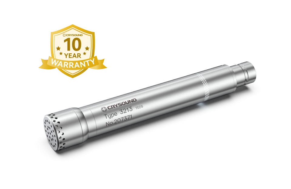
The Microphone That Goes Where Others Can't. 1/2" Prepolarized Free-Field | IP67 | -50°C to +125°C | Built for the Real World The Problem With Traditional NVH Microphones Every NVH engineer knows the frustration: you need accurate acoustic data, but the test environment is anything but laboratory-perfect. Rain. Dust. Engine bay heat at 120°C. Scandinavian winter at -40°C. Vibration. Shock. Road spray. Traditional measurement microphones weren't built for this. They're precision instruments designed for controlled environments - fragile, temperature-sensitive, and one drop away from an expensive recalibration. So engineers compromise: they protect the microphone instead of optimizing the measurement, or they accept degraded data from sensors pushed beyond their limits. CRY3213 changes this equation entirely. A Game Changer for NVH Testing The CRY3213 is the first NVH measurement microphone that delivers laboratory-grade accuracy in the harshest real-world conditions - without compromise, without babysitting, without excuses. What You Get What It Means -50°C to +125°C operating range Test in Arctic cold or next to a turbo manifold - same accuracy, same reliability IP67 dust & water protection Full immersion protection. Rain, road spray, pressure washing - it keeps measuring Ruggedized, vibration-resistant design Survives the shocks and vibrations of real-world vehicle testing without signal degradation 50 mV/Pa sensitivity High output for excellent signal-to-noise ratio, even in quiet cabin measurements 3.15 Hz - 20 kHz (±2 dB) Full audible bandwidth plus infrasound - captures everything from tire cavity resonance to HVAC hiss This isn't an incremental improvement. It's a new category: the ruggedized precision NVH microphone. Why CRY3213 Is Different 1. Extreme Temperature Performance Most measurement microphones spec a conservative operating range: 0°C to 50°C, maybe -10°C to 60°C with reduced performance. That's fine for a lab. It's useless for: Cold climate testing in Arjeplog, Sweden (-35°C) or Northern China (-40°C) Under-hood measurements where temperatures routinely exceed 100°C near exhaust manifolds and turbochargers Thermal cycling tests that swing from frozen to furnace in minutes CRY3213 operates at -50°C to +125°C with specified accuracy. No warm-up drift. No thermal shutdown. No recalibration needed between temperature extremes. When your competitors are swapping frozen microphones in the parking lot, your CRY3213 is still collecting data. 2. IP67: Truly Weatherproof IP67 means: - 6 = Total dust ingress protection (dust-tight) - 7 = Protected against temporary immersion in water (up to 1 meter, 30 minutes) For NVH testing, this translates to: - Pass-by noise testing in rain - no test cancellations, no scrambling for covers - Road spray and puddle testing - mount microphones at wheel height without worry - Tropical humidity environments - no condensation-related signal drift - Outdoor long-term monitoring - deploy and forget Most competitors either lack IP ratings entirely or max out at IP55 (limited dust/splash protection). CRY3213's IP67 is the highest protection class available in a precision NVH microphone. 3. Ruggedized and Vibration-Resistant Traditional condenser microphones are delicate by nature - thin diaphragms, precision air gaps, tight tolerances. The CRY3213 is engineered differently: Shock-resistant construction - survives drops, bumps, and the everyday abuse of field testing Power-on LED indicator - instant visual confirmation that the microphone is active and powered Vibration-isolated design - rejects mechanical vibration that would contaminate acoustic measurements on engine test benches and vehicle structures Robust cable and connector - designed for repeated connect/disconnect cycles in field conditions This means you can mount it on the vehicle, not just near it. Engine mounts, chassis rails, wheel arches - places where traditional microphones would fail from vibration alone. 4. No-Compromise Acoustic Performance Ruggedized doesn't mean reduced performance. CRY3213 delivers: Sensitivity: 50 mV/Pa (-26 dB re 1V/Pa) - matching premium lab microphones Frequency Response: 3.15 Hz to 20 kHz (±2 dB) - the full NVH bandwidth Dynamic range up to 136 dB - handles everything from quiet cabin to high-SPL engine bay measurements Low-frequency extension to 3.15 Hz - critical for tire cavity resonance (180-250 Hz), body boom (30-60 Hz), and powertrain low-order vibrations Prepolarized design - no external polarization voltage needed; plug-and-play with any IEPE/CCP input Application Scenarios Automotive NVH - Where CRY3213 Shines Application Environment Why CRY3213 Powertrain Noise Engine bay, 80-120°C, heavy vibration Temperature range + vibration resistance Road Noise Testing Outdoor, all weather, road spray IP67 + wide temperature range Wind Noise Testing Wind tunnel or outdoor, high airflow Ruggedized + dust protection Pass-by Noise (ISO 362) Outdoor, rain or shine, year-round IP67 enables all-weather testing Cold Climate Validation Arctic conditions, -30°C to -50°C -50°C low-end operating range EV Motor Whine Analysis Near e-drive, electromagnetic interference High sensitivity + vibration isolation Squeak & Rattle Interior, door panels, dashboard Full bandwidth down to 3.15 Hz Production Line EOL Test Factory floor, dust, temperature swings IP67 + rugged design for 24/7 industrial use Beyond Automotive CRY3213's extreme environmental specs make it equally valuable in: Aerospace: Engine run-up testing, cabin noise certification, flight testing Rail: Exterior and interior noise measurements per EN/ISO standards Heavy Industry: Turbine noise monitoring, compressor testing, outdoor environmental noise Energy: Wind turbine noise assessment in extreme weather conditions CRY3213 vs. The Competition How does CRY3213 stack up against the industry's most common NVH microphones? Feature CRY3213 B&K Type 4189 GRAS 46AE Temperature Range -50°C to +125°C -10°C to +50°C -10°C to +50°C IP Rating IP67 Not rated Not rated Vibration Resistance Yes (ruggedized) No No Sensitivity 50 mV/Pa 50 mV/Pa 50 mV/Pa Frequency Range 3.15 Hz - 20 kHz 6.3 Hz - 20 kHz 3.15 Hz - 20 kHz Size (1/2") ✅ ✅ ✅ Prepolarized ✅ ✅ ✅ Warranty 10 years 2 years 2 years All-Weather Field Use Yes Limited Limited The bottom line: Same precision. Same sensitivity. Dramatically more capable in real-world conditions. And backed by a 10-year warranty that says we stand behind it. Technical Specifications Parameter Value Type 1/2" Free-field, Prepolarized IEC Standard IEC 61094 WS2F Sensitivity (±2 dB) 50 mV/Pa, -26 dB re 1V/Pa Frequency Response (±2 dB) 3.15 Hz - 20 kHz Dynamic Range (re. 20 µPa) xx dB(A) - 136 dB Capacitance @250 Hz 15 pF Maximum Output Voltage > 8.0 V Power Supply IEPE (2-20 mA) Connector BNC Operating Temperature -50°C to +125°C Storage Temperature -25°C to +70°C Operating Humidity 0-90% RH, non-condensing IP Rating IP67 (dust-tight, waterproof) Dimensions (with grid) Ø14.5 mm × 92 mm Polarization 0 V (prepolarized) Note: Weight TBC. Frequently Asked Questions Q: Can I use CRY3213 with my existing NVH data acquisition system? A: Yes. CRY3213 is a prepolarized (0V) IEPE/CCP microphone, compatible with any standard constant-current input - including systems from Siemens (SCADAS), HBK (LAN-XI), Dewesoft, National Instruments, HEAD acoustics, and others. Q: How does it handle rapid temperature changes during thermal cycling tests? A: CRY3213 is designed for continuous operation across its full -50°C to +125°C range, including rapid transitions. The thermal compensation ensures sensitivity stability without requiring recalibration between temperature extremes. Q: Is it suitable for permanent outdoor installation? A: Yes. With IP67 protection, CRY3213 is suitable for long-term outdoor deployment. For extended installations, we recommend using the optional outdoor windscreen accessory to minimize wind-induced noise. Q: What's the advantage over array microphones for NVH? A: Array microphones (MEMS-based) offer cost advantages for large-channel setups but typically have narrower dynamic ranges and less environmental protection. CRY3213 provides IEC 61094-compliant precision for reference-quality measurements in conditions where array microphones can't survive. Q: 10-year warranty - what does it cover? A: CRYSOUND's 10-year warranty covers manufacturing defects and sensitivity drift beyond specification. It's one of the longest warranties in the measurement microphone industry, reflecting our confidence in CRY3213's long-term reliability. Ready to Upgrade Your NVH Testing? Stop compromising between precision and durability. CRY3213 delivers both. Request a Quote → Download Datasheet (PDF) → Compare All CRYSOUND Microphones →
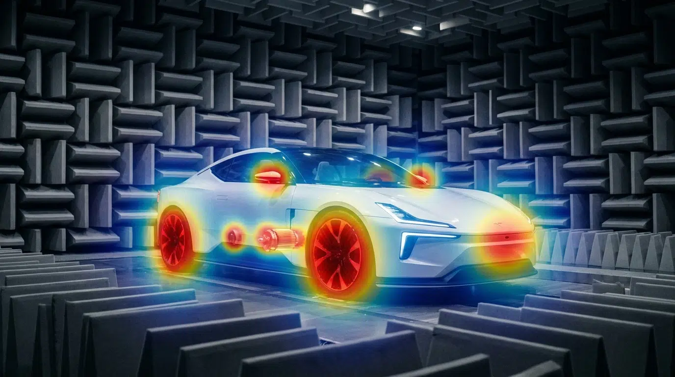
The Quiet EV Paradox: Why Electric Cars Are Actually "Noisier" It sounds like a paradox - electric vehicles have no roaring engine, yet engineers are finding it harder than ever to achieve a truly quiet cabin. The truth is, when the low-frequency masking effect of the internal combustion engine disappears, every previously hidden noise becomes fully exposed: the high-frequency whine of the electric motor, the electromagnetic hum of the inverter, gear meshing vibrations, wind noise, road noise, even the squeak and rattle of interior trim - nothing can hide anymore. This isn't just a comfort issue. It's fundamentally redefining the automotive industry's approach to NVH (Noise, Vibration, and Harshness) testing. The global automotive NVH testing market is projected to grow from USD 3.51 billion in 2026 to USD 5.75 billion by 2034, at a CAGR of 6.4%. The core driver behind this growth? The electrification revolution. What New Noise Challenges Do EVs Bring? A Fundamental Shift in Frequency Range Traditional ICE vehicle NVH work focuses on the 20-2,000 Hz low-frequency range - engine firing, exhaust systems, crankshaft vibrations. Electric vehicles are fundamentally different: Noise Source Typical Frequency Range Characteristics Electric motor electromagnetic noise 500-5,000 Hz Sharp tonal noise, varies linearly with speed Inverter switching noise 4,000-10,000+ Hz High-frequency hum, related to PWM frequency Gear meshing noise 800-3,000 Hz Particularly prominent in single-speed reducers Battery charger noise 8,000-20,000 Hz Near-ultrasonic range, at the edge of human perception Wind / Road noise 200-4,000 Hz Highly exposed without engine masking ICE vs EV: The fundamental shift in noise frequency characteristics Key insight: EV noise problems shift from low frequencies to mid-high frequencies (and even ultrasonic ranges). The 100Hz-5kHz range is where most critical NVH issues reside-precisely where human hearing is most sensitive. Traditional NVH testing methods and frequency ranges may no longer be sufficient. New Noise Sources, New Localization Challenges In the ICE era, the assumption that "the engine is the dominant noise source" made things relatively straightforward. In EVs, noise sources become more distributed and complex: Electric drive system: The motor + inverter + reducer form a highly coupled noise system Thermal management: Battery cooling pumps and fans become dominant noise sources at low speeds Regenerative braking: Changes in inverter operating modes during energy recovery produce transient noise Structural transmission paths: Lightweight body structures (aluminum alloy, carbon fiber) have fundamentally different sound insulation characteristics compared to traditional steel This means engineers face a core challenge: How do you quickly and accurately locate the root cause among multiple distributed, dynamically changing noise sources? Sound Quality Design: From "Reducing Noise" to "Crafting Sound" NVH engineering in the EV era is no longer just about "minimizing noise." Consumers expect a carefully designed sound experience: Acceleration should feel "high-tech" without being harsh The cabin should be quiet, but not so silent that it makes the driver uneasy Different driving modes (Sport / Comfort / Eco) should deliver differentiated acoustic feedback This demand for "Sound Design" is expanding NVH testing from pure engineering validation into subjective sound quality evaluation and brand-level acoustic identity. Why Acoustic Cameras Are Becoming Essential for EV NVH Facing these new challenges, traditional NVH testing tools - single-point microphones, accelerometers - remain important but are no longer sufficient for every scenario. Acoustic cameras are filling this gap. Core Advantages of Acoustic Cameras 1. Real-Time Noise Source Visualization Traditional methods require densely placing microphone arrays on the target object - time-consuming and labor-intensive. Acoustic cameras use beamforming technology to generate a noise source heatmap in a single capture, instantly showing "where the noise is and how loud it is." Typical scenario: An EV prototype running on a test bench, the acoustic camera aimed at the electric drive system, instantly revealing that an 800 Hz resonance originates primarily from the right side of the motor - the entire localization process takes less than 5 minutes. Engineer conducting noise source localization test Automotive NVH detection and optimization 2. Wide Frequency Coverage EV noise spans from hundreds of hertz (gear meshing) to tens of thousands of hertz (inverter switching noise) - an enormous frequency range. Critical consideration for NVH: Most EV noise issues occur in the 100Hz-5kHz range-gear meshing, motor electromagnetic noise, wind leaks, HVAC systems. Traditional acoustic imaging cameras (limited to frequencies above 5 kHz) cannot capture these noise sources. Take the CRYSOUND SonoCam Pi (CRY8500 Series) as the ideal example: its 208 MEMS microphone array provides: Beamforming frequency range: 400 Hz - 20 kHz (covers the entire NVH audible spectrum) Near-field acoustic holography range: 40 Hz - 20 kHz (captures low-frequency road noise and structural vibration) Array size: >30 cm (optimized for low-frequency spatial resolution) This makes SonoCam Pi uniquely suited for full-spectrum EV NVH testing-from low-frequency road noise to high-frequency motor whine, all in a single handheld device. 3. Non-Contact Measurement EV electric drive systems are highly integrated and spatially compact. The non-contact measurement approach of acoustic cameras means: No disassembly of any components required No interference with the operating state of the system under test Rapid quality inspection directly on the production line 4. Portability Modern handheld acoustic cameras like the SonoCam Pi can be taken directly to proving grounds, production lines, or customer sites, no complex setup required. Typical Application Scenarios in EV NVH Scenario Application E-drive system NVH Locating order-based noise contributions from motors, inverters, and reducers Pass-by noise testing Analyzing noise source distribution as vehicles pass by Interior squeak & rattle tracking Locating noise from dashboards, doors, seats, and trim End-of-line production QC Rapid online detection of abnormal noise, replacing subjective human judgment Wind tunnel / Semi-anechoic chamber High-precision noise source localization and sound power analysis Real-World Case Study: OEM Dynamic Road Testing Client: A leading Chinese OEMLocation: An OEM test center, internal test trackObjective: Identify in-cabin noise sources during dynamic driving conditions CRY8500 Series SonoCam Pi acoustic cameras Test Setup Device:SonoCam Pi acoustic camera Measurement positions:Rear seat and front passenger seat Target areas:Left and right B-pillars (rear cabin area) Test mode:Beamforming app Frequency range:3,550 Hz - 7,550 Hz Dynamic range:5 dB Key Results SonoCam Pi successfully localized noise sources in real-time during vehicle motion, providing actionable data for OEM's NVH engineering team. The test demonstrated: Real-time localization during dynamic conditions: Unlike fixed laboratory setups, SonoCam Pi captured noise distribution while the vehicle was in motion on the test track Precise frequency-band analysis: By focusing on the 3,550-7,550 Hz range (critical for perceived cabin noise), engineers pinpointed specific contributors rather than measuring overall SPL Rapid testing workflow: Complete B-pillar area scan in minutes, not hours Noise Source Localization Results Key Insight: Traditional microphone arrays would require the vehicle to be stationary in a semi-anechoic chamber. SonoCam Pi enabled on-track diagnostics, dramatically reducing testing time and enabling rapid iteration during vehicle development. Future Trends - What's Next for EV NVH Testing? AI-Driven Noise Classification Machine learning is being integrated into NVH testing workflows: automatically identifying noise types, determining whether anomalies exist, and predicting potential quality issues. The high-dimensional data captured by acoustic cameras is naturally suited for AI analysis. Digital Twins and Simulation-Test Integration Simulation (CAE) predicts noise performance → Acoustic camera validates through physical measurement → Data feeds back to optimize the simulation model. This closed-loop approach is becoming the standard workflow for major OEMs. New Challenges in the Solid-State Battery Era Solid-state batteries have different mechanical properties compared to liquid lithium-ion batteries. Their vibration transmission characteristics and thermal management approaches will introduce new NVH challenges. Stricter Regulations Pass-by noise testing is the fastest-growing NVH sub-segment (CAGR 7.11%), with UNECE pushing for stricter standardized testing requirements, including indoor pass-by testing protocols. Conclusion: The Value of Acoustic Testing, Redefined for the EV Era Electrification hasn't made cars quieter - it has made noise challenges more complex, more nuanced, and more valuable to solve. For automotive OEMs, Tier 1 suppliers, and testing service providers, investing in the right NVH testing equipment is no longer a "nice-to-have" - it's foundational infrastructure for competitiveness. Acoustic cameras-especially those capable of capturing the critical 100Hz-5kHz NVH frequency range-are evolving from "useful auxiliary tools" to "indispensable standard equipment." The CRYSOUND SonoCam Pi stands out as the only handheld acoustic camera that combines: Low-frequency capability (400 Hz beamforming, 40 Hz holography) High spatial resolution (208 microphones, >30 cm array) Near-field + far-field measurements in a single system Portability (handheld, <3 kg, production-ready) Learn more: CRYSOUND SonoCam Pi (CRY8500 Series) → Contact us for NVH testing solutions →

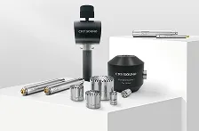
A measurement microphone is not just any microphone - it is a precision acoustic sensor designed for traceable, repeatable sound pressure measurement. This guide covers how they work, the different types available, key specifications to compare, and how to select the right one for your application. What Is a Measurement Microphone? A measurement microphone is a high-precision acoustic transducer engineered to convert sound pressure into an electrical signal with known accuracy. Unlike studio or consumer microphones that are designed to make audio "sound good," a measurement microphone is designed to be truthful - its output must faithfully represent the actual sound pressure at the measurement point. The defining characteristics of a measurement microphone include: Known, stable sensitivity (expressed in mV/Pa) that can be traced to national or international standards Flat, well-characterized frequency response under defined sound-field conditions Wide dynamic range with low distortion from noise floor to maximum SPL Traceable calibration using pistonphones or acoustic calibrators Environmental stability - minimal drift due to temperature, humidity, and atmospheric pressure changes In practical terms, a measurement microphone is the front-end sensor of a metrology-grade measurement chain. Every specification - from the data acquisition system to the analysis software - depends on the microphone providing an accurate representation of the acoustic environment. For a deeper comparison between measurement and regular microphones, see our article: Differences Between Measurement Microphones and Regular Microphones. How Measurement Microphones Work The Condenser Principle How a condenser measurement microphone converts sound pressure into an electrical signal Nearly all measurement microphones are condenser (capacitor) microphones. The core transduction mechanism is simple but elegant: A thin metallic diaphragm is stretched in front of a rigid backplate, separated by a small air gap The diaphragm and backplate form a capacitor When sound pressure deflects the diaphragm, the gap changes, altering the capacitance With a constant charge on the capacitor, the capacitance change produces a proportional voltage change This voltage change is the microphone's output signal. A preamplifier, typically located immediately behind the capsule, converts the high-impedance signal from the capacitor into a low-impedance signal that can travel through cables to the data acquisition system. Polarization: External vs. Prepolarized Externally polarized (left) vs. prepolarized electret (right) microphone types The condenser principle requires a polarization voltage to maintain a charge on the capacitor. There are two approaches: Externally polarized microphones receive their polarization voltage (typically 200V) from an external power supply through the preamplifier. These microphones are considered the gold standard for the highest-accuracy laboratory measurements because: - The polarization voltage is stable and well-defined - No aging effects from the polarization source - Best long-term stability Prepolarized (electret) microphones use a permanently charged PTFE (Teflon) layer on the backplate to maintain polarization. Advantages include: - No external polarization supply needed - simplifies the signal chain - More resistant to humidity (no risk of charge leakage at high humidity) - Better suited for field measurements and harsh environments - Modern prepolarized microphones achieve accuracy comparable to externally polarized models Feature Externally Polarized Prepolarized Polarization source External 200V supply Built-in electret layer Best for Lab/reference measurements Field and industrial use Humidity tolerance Sensitive above ~90% RH Excellent, even in high humidity Long-term stability Excellent Very good (modern designs) Signal chain Requires compatible power supply Works with standard IEPE/ICP preamplifiers The Preamplifier The preamplifier is a critical but often overlooked component. It serves two functions: Impedance conversion: Transforms the microphone's extremely high output impedance (~GΩ) into a low impedance suitable for cable transmission Signal conditioning: Provides the power for IEPE/ICP operation or the polarization voltage for externally polarized capsules A matched microphone-preamplifier set ensures optimal performance. This is why measurement microphones are often sold as complete sets with a matched preamplifier - the combined system is calibrated and characterized as a unit. Types of Measurement Microphones Measurement microphones are classified along two primary axes: sound-field type and physical size. By Sound-Field Type The choice of microphone type depends on the acoustic environment where measurements will be taken. Free-Field Microphones A free-field microphone is designed to measure sound arriving from a single direction in an environment free of reflections (such as an anechoic chamber or outdoors). The microphone's frequency response is compensated for the acoustic diffraction effects caused by its own physical presence in the sound field. When to use: Outdoor measurements, anechoic chamber testing, source identification, environmental noise monitoring, any scenario where sound arrives predominantly from one direction. Orientation: Point the microphone directly at the sound source (0° incidence). Pressure-Field Microphones A pressure-field microphone measures the actual sound pressure at a surface or in a sealed cavity. It has the flattest possible response when the sound field is uniform across the diaphragm - which occurs in small cavities, couplers, or at surfaces where the microphone is flush-mounted. When to use: Coupler measurements (headphone and earphone testing), hearing aid testing, measurements in small cavities, flush-mounted surface measurements, acoustic impedance measurements. Orientation: The microphone diaphragm is placed at or within the measurement surface. Random-Incidence Microphones A random-incidence (diffuse-field) microphone is optimized for environments where sound arrives from all directions simultaneously - such as reverberant rooms. Its frequency response is a weighted average of responses at all angles of incidence. When to use: Reverberation chamber measurements, environmental noise in reflective spaces, any situation where sound arrives from multiple directions. Microphone Type Sound Field Typical Application Orientation Free-field Sound from one direction Outdoor noise, anechoic testing, source ID Point at source Pressure-field Uniform pressure (cavity) Coupler testing, headphones, hearing aids Flush with surface Random-incidence Sound from all directions Reverberant rooms, diffuse environments Any orientation Three microphone types for different acoustic environments: free-field, pressure-field, and random-incidence By Physical Size Measurement microphone capsules come in three standard sizes, each with distinct trade-offs: 1-Inch Microphones The largest standard size. High sensitivity and low noise floor make them ideal for measuring very quiet environments. Sensitivity: ~50 mV/Pa (highest) Frequency range: Up to ~8-16 kHz Best for: Low-frequency and low-level measurements, environmental noise monitoring, building acoustics Limitation: Large size limits upper frequency range due to diffraction effects 1/2-Inch Microphones The most widely used size. Offers a good balance between sensitivity, frequency range, and physical size. Sensitivity: ~12.5-50 mV/Pa Frequency range: Up to 20-40 kHz Best for: General-purpose acoustic measurements, NVH testing, product R&D, sound level meters Why it's popular: Versatile enough for most applications; fits standard sound level meter bodies 1/4-Inch Microphones The smallest standard size. Low sensitivity but the widest frequency range. Sensitivity: ~1.6-16 mV/Pa Frequency range: Up to 40-100 kHz Best for: High-frequency measurements, ultrasonic applications, small coupler measurements, acoustic array elements Trade-off: Higher noise floor requires louder sound sources for accurate measurement Size comparison: 1-inch (CRY3101), 1/2-inch (CRY3203), and 1/4-inch (CRY3401) measurement microphone capsules Size Sensitivity (typical) Frequency Range Dynamic Range Best For 1 inch 50 mV/Pa 4 Hz - 16 kHz 15-146 dBA Low-frequency, quiet environments 1/2 inch 12.5-50 mV/Pa 3 Hz - 40 kHz 16-164 dBA General-purpose, NVH, SLM 1/4 inch 1.6-16 mV/Pa 4 Hz - 100 kHz 32-174 dBA High-frequency, ultrasonic, arrays Key Specifications Explained When comparing measurement microphones, these specifications matter most: Sensitivity Sensitivity defines how much electrical output the microphone produces for a given sound pressure. Expressed in mV/Pa (millivolts per Pascal) or dB re 1V/Pa. Higher sensitivity = better signal-to-noise ratio at low sound levels Lower sensitivity = higher maximum SPL before distortion There is always a trade-off between sensitivity and maximum SPL Frequency Response The frequency range over which the microphone provides accurate measurements, typically specified within ±2 dB or ±1 dB. The useful range depends on: - Microphone size (smaller = wider range) - Sound-field type (free-field compensation extends the useful range) - Mounting configuration Dynamic Range The span between the lowest measurable level (noise floor) and the highest level before a specified distortion threshold (typically 3% THD). A wider dynamic range means the microphone can handle a greater variety of measurement scenarios. Self-Noise (Equivalent Noise Level) The inherent electrical noise of the microphone, expressed as an equivalent sound pressure level in dBA. Lower is better - critical for measuring quiet environments. 1-inch microphones: ~15-18 dBA (quietest) 1/2-inch microphones: ~16-28 dBA 1/4-inch microphones: ~32-46 dBA Stability and Temperature Coefficient Long-term sensitivity drift and sensitivity change with temperature. Important for: - Permanent monitoring installations (fixed outdoor microphones) - Measurements in extreme environments (engine test cells, climatic chambers) - Ensuring measurement results are comparable over months or years IEC Standards Compliance Measurement microphones are classified according to IEC 61094 series: - IEC 61094-1: Primary calibration by reciprocity method - IEC 61094-4: Specifications for working standard microphones (laboratory use) - IEC 61094-5: Working standard microphones for in-situ (field) use Sound level meters incorporating measurement microphones must comply with: - IEC 61672-1: Class 1 (precision) or Class 2 (general purpose) How to Choose the Right Measurement Microphone How to select the right measurement microphone for your application Step 1: Identify Your Sound Field Your Measurement Scenario Recommended Type Outdoor environmental noise Free-field Anechoic chamber testing Free-field Headphone/earphone coupler Pressure-field Hearing aid testing Pressure-field Reverberant room Random-incidence Surface-mounted on a machine Pressure-field General factory noise Free-field or random-incidence Step 2: Determine Required Frequency Range Application Minimum Frequency Range Building acoustics 20 Hz - 8 kHz Environmental noise 20 Hz - 12.5 kHz General acoustic testing 20 Hz - 20 kHz NVH (automotive) 20 Hz - 20 kHz Electroacoustic product testing 20 Hz - 40 kHz Ultrasonic measurements 20 Hz - 100 kHz Step 3: Match the Dynamic Range to Your Environment Quiet environments (recording studios, anechoic chambers): Choose high-sensitivity microphones (50 mV/Pa, 1/2" or 1") with low self-noise Industrial environments (factory floors, engine test cells): Choose lower-sensitivity microphones (4-12.5 mV/Pa, 1/4" or 1/2") with high maximum SPL Wide-range applications: Choose microphones with the widest dynamic range available Step 4: Consider Environmental Conditions High humidity or outdoor use: Prepolarized microphones are recommended Extreme temperatures: Check the microphone's operating temperature range and temperature coefficient Dusty or wet environments: Look for IP-rated solutions (e.g., IP67 for NVH field testing) Hazardous areas: Check for ATEX/IECEx certification if required Step 5: Evaluate the Complete System A measurement microphone does not work alone. Consider: - Preamplifier compatibility: Matched sets ensure specified performance - Data acquisition system: Input impedance, voltage range, and sampling rate must match - Calibration infrastructure: Do you have access to a pistonphone or acoustic calibrator? - Software ecosystem: Can your analysis software import calibration data and apply corrections? Applications Electroacoustic Product Testing Testing loudspeakers, headphones, earphones, and hearing aids requires microphones that can accurately capture the device's frequency response, distortion, and directivity. Pressure-field microphones are used in couplers (IEC 60318 ear simulators), while free-field microphones are used in anechoic chambers. Automotive and Aerospace NVH NVH (Noise, Vibration, and Harshness) engineers use measurement microphones to characterize cabin noise, identify noise sources, evaluate sound packages, and perform transfer path analysis. Requirements include wide frequency range, high dynamic range, and robustness for field use. Environmental and Community Noise Monitoring Long-term outdoor noise monitoring stations require microphones with excellent stability over months or years, low temperature sensitivity, and tolerance to humidity, rain, and wind. Windscreens and weather protection accessories are essential. Production Line Quality Control In manufacturing, measurement microphones integrated into automated test systems verify that every loudspeaker, headphone, or microphone meets specifications before shipping. Speed, repeatability, and consistency are critical - the microphone must produce identical results across thousands of units per day. Building and Architectural Acoustics Measuring reverberation time, sound insulation, and HVAC noise requires accurate low-frequency performance and the ability to work in diffuse sound fields. Random-incidence microphones are often preferred. Acoustic Research and Standards Laboratories Primary and secondary calibration laboratories, standards organizations, and university research groups require the highest-accuracy microphones - typically externally polarized, laboratory-grade capsules calibrated by reciprocity methods. Sound Source Localization and Beamforming Microphone arrays used in acoustic cameras and beamforming systems require large numbers of measurement microphones with tightly matched sensitivity and phase response. 1/4-inch microphones are preferred for arrays due to their small size and wide frequency range. For more on acoustic imaging technology, see our guide on acoustic cameras. Noise Regulation Compliance Regulatory compliance measurements - workplace noise (ISO 9612), environmental noise (ISO 1996), product noise emission (ISO 3744/3745) - require Class 1 or Class 2 measurement microphones as specified in IEC 61672. Documentation of calibration traceability is mandatory for compliance reporting. CRYSOUND Measurement Microphone Solutions CRYSOUND's CRY3000 series measurement microphones cover the full range of sizes, field types, and applications - from laboratory reference measurements to rugged field testing. Complete Size Coverage: 1/4", 1/2", and 1" Model Size Field Type Sensitivity Frequency Range Application CRY3101-S01 1" Free-field 50 mV/Pa 4 Hz - 16 kHz Low-frequency, quiet environments CRY3203-S01 1/2" Free-field 50 mV/Pa 3.15 Hz - 20 kHz General acoustic testing CRY3261-S02 1/2" Free-field 450 mV/Pa 10 Hz - 16 kHz Ultra-high sensitivity CRY3201-S01 1/2" Free-field 12.5 mV/Pa 3.15 Hz - 40 kHz Extended high-frequency CRY3401-S01 1/4" Free-field 15.8 mV/Pa 4 Hz - 40 kHz High-frequency testing CRY3403-S01 1/4" Free-field 4 mV/Pa 4 Hz - 90 kHz Ultrasonic measurements CRY3202-S01 1/2" Pressure 12.5 mV/Pa 3.15 Hz - 20 kHz Coupler and cavity testing CRY3402 1/4" Pressure 1.6 mV/Pa 4 Hz - 100 kHz High-frequency pressure field CRY3406-S01 1/4" Pressure 15.8 mV/Pa 4 Hz - 40 kHz Low-noise pressure field CRY3213: Purpose-Built for NVH The CRY3213 NVH Measurement Microphone is specifically designed for the demanding conditions of automotive and industrial NVH testing: IP67 protection: Fully dust-tight and submersible - operates reliably in engine bays, test tracks, and climatic chambers Extended temperature range: -50°C to 125°C, covering extreme hot and cold testing scenarios Free-field response: 3.15 Hz to 20 kHz, optimized for the frequency range relevant to cabin noise, powertrain NVH, and road noise 50 mV/Pa sensitivity: High enough for quiet cabin measurements, robust enough for engine noise Matched Microphone-Preamplifier Sets Every CRYSOUND measurement microphone set includes a matched preamplifier, factory-calibrated as a complete system. This eliminates the guesswork of mixing microphones and preamplifiers from different sources, and ensures that the combined frequency response, noise floor, and dynamic range meet the published specifications. Calibration and Traceability All CRYSOUND measurement microphones ship with individual calibration certificates traceable to national standards. For ongoing measurement assurance, see our guide on measurement microphone calibration. Explore CRYSOUND Measurement Microphones → Frequently Asked Questions What is the difference between a measurement microphone and a regular microphone? A measurement microphone is designed for accuracy and traceability - its output must truthfully represent the sound pressure at the measurement point. A regular microphone is designed for audio quality, often with intentional frequency shaping to enhance speech clarity or musical timbre. For a detailed comparison, read Measurement vs. Regular Microphones. Do I need to calibrate my measurement microphone? Yes. Regular calibration - at minimum before each measurement session using an acoustic calibrator - ensures your results are accurate and traceable. Periodic laboratory recalibration (typically annually) verifies long-term stability. Learn more about microphone calibration. Can I use a 1/2-inch microphone for ultrasonic measurements? Standard 1/2-inch microphones typically reach up to 20-40 kHz, which is insufficient for many ultrasonic applications. For measurements above 40 kHz, a 1/4-inch microphone is recommended - models like the CRY3403 reach 90 kHz, while the CRY3402 reaches 100 kHz. What does "free-field" vs. "pressure-field" mean? A free-field microphone is optimized for measuring sound arriving from one direction in open space. A pressure-field microphone is optimized for measuring sound pressure in enclosed cavities or at surfaces. The difference is in how the microphone compensates for acoustic diffraction effects at high frequencies. How do I choose between externally polarized and prepolarized? For laboratory reference measurements in controlled environments, externally polarized microphones offer the best long-term stability. For field measurements, industrial applications, or environments with high humidity, prepolarized microphones are more practical and equally accurate with modern designs. What IP rating do I need for outdoor or industrial use? For NVH field testing and outdoor measurements, IP67 (dust-tight, waterproof) provides the best protection. The CRY3213 is specifically designed for these conditions. For general lab use, IP protection is typically not required. Need help selecting the right measurement microphone for your application? Contact CRYSOUND for expert guidance based on your specific measurement requirements.


