

As A²B microphones and sensors are increasingly adopted in automotive applications, the demand for reliable testing in both R&D and production is also growing. This article explains why A²B testing matters, highlights the advantages of A²B over traditional analog cabling in terms of interconnect and scalability, outlines key measurement KPIs (such as frequency response, THD+N, phase/polarity, and SNR), and presents a typical test-bench setup along with the corresponding solution configuration.
Why A²B Microphone and Sensor Testing Matters
In-cabin audio is no longer just "music playback". Modern vehicles depend on high-performance acoustic sensing for hands-free calling, in-cabin communication, voice assistants, ANC/RNC, and more-and these features increasingly rely on multiple microphones and even accelerometers deployed around the cabin. ADI notes that the rapid expansion of audio-, voice-, and acoustics-related applications is a key trend, and that new digital microphone and connectivity approaches are enabling broader adoption.
To deliver consistent performance, teams need a test workflow that is repeatable across different node positions, harness lengths, and configurations-without turning every debug session into a custom project.
The Interconnect Shift: From Shielded Analog Cables to Digital A²B
Historically, scaling microphone counts often meant scaling shielded analog cabling, which adds weight, cost, and integration burden-sometimes limiting these features to premium vehicle segments.
A²B (Automotive Audio Bus) addresses that interconnect problem by enabling a scalable, networked digital audio architecture with deterministic behavior-exactly what timing-sensitive acoustic applications need. Figures a and b show how such a design may be realized with the traditional analog and the digital A²B systems, respectively.
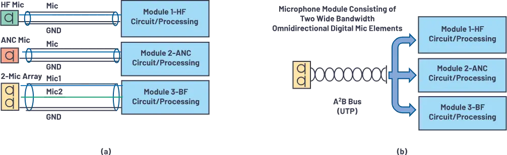
(b) Digital system design with digital mic elements (A²B technology and UTP wires).
What You'll Measure: Key A²B Microphone KPIs
- Frequency Response (FR)
- THD+N
- Phase / polarity (and channel-to-channel consistency for arrays)
- SNR
- AOP (if required by your program/spec)
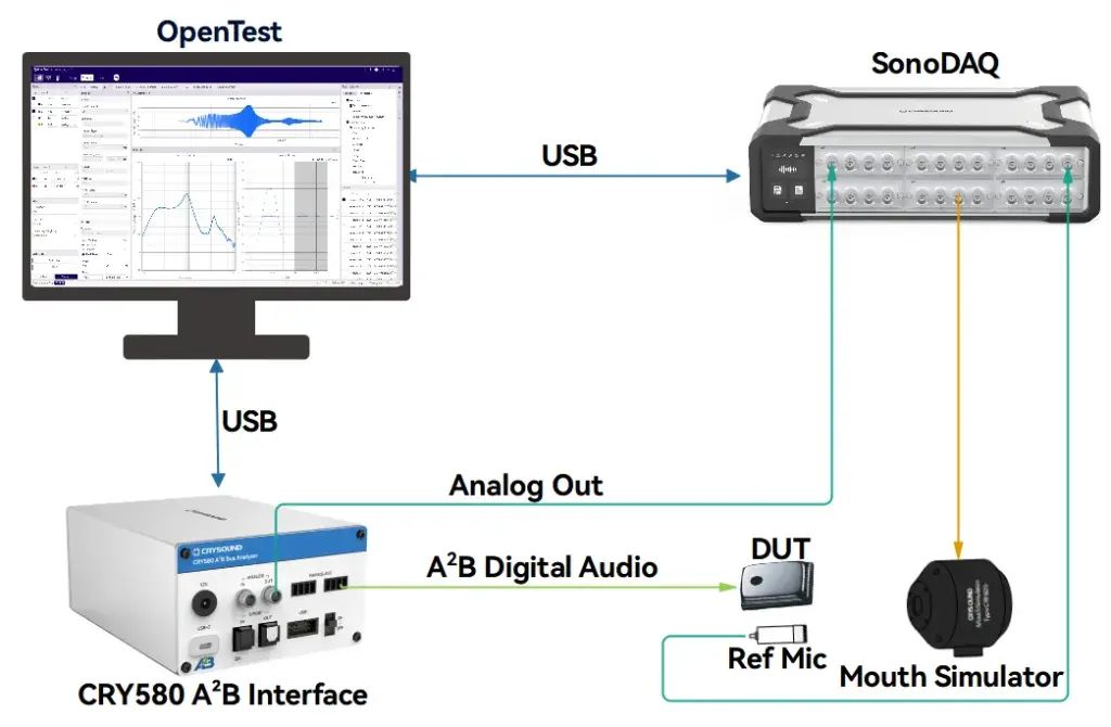
Typical Block Diagram-What the Bench Looks Like
At CRYSOUND, we provide more than just the CRY580 A²B interface. We offer a full automotive audio testing solution, including audio acquisition cards, microphones and sensors, acoustic sources, custom fixtures, acoustic test boxes, and vibration shakers, delivering a complete and streamlined testing experience.
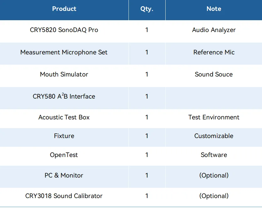
Solution BOM List
The value of end-to-end delivery: reducing system integration time and minimizing coordination costs between multiple suppliers. We cover everything from R&D to production line testing.
If you'd like to learn more about A²B testing, please fill out the Get in touch form below and we'll reach out shoutly.
CRY2831 Class 2 Sound Level Meter
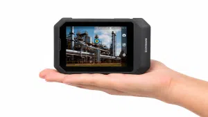
CRY8024 SonoCam Pocket Acoustic Camera
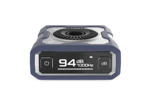
CRY3016 Sound Calibrator
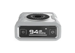
CRY3012 Sound Calibrator
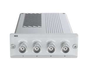
CRY5011 IEPE Analog In - IED
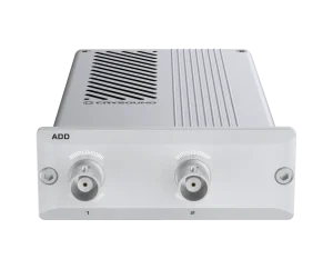
CRY5085 Analog Output Class D 10W - ADD
CRY2831 Class 2 Sound Level Meter
CRY8024 SonoCam Pocket Acoustic Camera
CRY3016 Sound Calibrator
CRY3012 Sound Calibrator
CRY5011 IEPE Analog In - IED
